« Retrocube » : différence entre les versions
Aucun résumé des modifications |
|||
| Ligne 2 : | Ligne 2 : | ||
This first part describe the hardware of this project. | This first part describe the hardware of this project. | ||
== | == Retro Gaming console in a GameCube == | ||
For this project, you will need: | |||
* A GameCube case | * A GameCube (Only the case will be reused, a broken one is fine!) | ||
* A Raspberry Pi | * A Raspberry Pi running Retro Pi | ||
* 2 GameCube | * 2 GameCube gamepads | ||
Goal : | |||
* | * Gamepad compatible menus ( no need for a keyboard) | ||
* | * Functional Gamecube’s power button | ||
* | * Functional Gamecube’s reset button | ||
* | * Gamepads plugged in the original connectors | ||
* | * Power from the Gamecube’s power unit or any other supply unit | ||
== Hardware | == Hardware == | ||
=== | === Opening the Gamecube === | ||
The GameCube uses | The GameCube uses special heads. As it’s a rare head type, we’ll use a neat trick to open them: A Bic crystal pen! | ||
* Remove the ballpoint | (Note: They are really common in France, I’m kinda hoping it’s the same where you live) | ||
* Carefully, | To make you screwdriver: | ||
* | * Remove the ballpoint/ink | ||
* | * Carefully, heat up the end of the pen with a lighter until it’s « melty » | ||
* Apply the melty end on one of the screws and wait for the pen to cool down | |||
* Once hardened, you should be able to use it as a screwdriver! It’s that simple ;) | |||
<gallery> | <gallery> | ||
| Ligne 30 : | Ligne 32 : | ||
</gallery> | </gallery> | ||
=== GameCube | === GameCube disassembly === | ||
Safely | Safely take apart all the parts | ||
<gallery> | <gallery> | ||
| Ligne 44 : | Ligne 46 : | ||
</gallery> | </gallery> | ||
=== | === Gamepad Connectors === | ||
| Ligne 50 : | Ligne 52 : | ||
[[Fichier:GPIO.png|100px|GPIO (rev2 pi)]] | [[Fichier:GPIO.png|100px|GPIO (rev2 pi)]] | ||
Carefully identify each pins | Carefully identify each pins : | ||
[[Fichier:RaspberryPi GPIO.JPG|thumb|left|40px|RaspberryPi GPIO]] | [[Fichier:RaspberryPi GPIO.JPG|thumb|left|40px|RaspberryPi GPIO]] | ||
* 3.3V | * 3.3V | ||
| Ligne 61 : | Ligne 63 : | ||
<br /> | <br /> | ||
I found an adapter | I found an adapter from an old dvd reader to connect the GPIO to the GameCube front panel to easily connect wires to the GameCube original ribbon cable. | ||
Each ( port 1 and port 2 ) gamecube controller should be connected to | Each ( port 1 and port 2 ) gamecube controller should be connected to | ||
* Pin2 to PAD2 or PAD3 | * Pin2 to PAD2 or PAD3 | ||
| Ligne 77 : | Ligne 79 : | ||
</gallery> | </gallery> | ||
=== Power | === Power supply === | ||
My goal is to reuse the GC’s original power supply and to allow the use of a standard power supply. | |||
The original power switch and the fan | |||
To do so, you’ll need a DC/DC converter that will take any DC power under 24v to transform it in the 5V DC needed by the Pi. You can find that on ebay by searching "3A UBEC 5V". | |||
The original power switch and the fan are also functional : | |||
<gallery> | <gallery> | ||
Fichier:GameCube power supply.jpg|GameCube power supply | Fichier:GameCube power supply.jpg|GameCube power supply | ||
</gallery> | </gallery> | ||
You’ll need to place the DC/DC converter between the GC’s power supply and the Pi: | |||
<gallery> | <gallery> | ||
Fichier:GameCube power supply unit.jpg|GameCube power supply unit | Fichier:GameCube power supply unit.jpg|GameCube power supply unit | ||
</gallery> | </gallery> | ||
and the output of the power supply is | and the output of the power supply is powering the Pi. I do not use the micro USB port to power the pi because : | ||
* it's allow me to spare some space and put the sd card in front of the gamecube; | |||
* it's allow better connectivity. | |||
=== | === Result === | ||
The | The Raspberry pi’s SD card can be inserted in the gamecube’s memory port. | ||
The HDMI and Ethernet ports are | The HDMI and Ethernet ports from the Pi are prolongated to the GC’s ports | ||
Here is the result : | Here is the result : | ||
<gallery> | <gallery> | ||
| Ligne 103 : | Ligne 109 : | ||
</gallery> | </gallery> | ||
== Software | == Software == | ||
The | The Pi is running RetroPie. | ||
=== RetroPie installation and configuration === | === RetroPie installation and configuration === | ||
You’ll need to download RetroPie from their website [[petrockblock]]http://blog.petrockblock.com/retropie/retropie-downloads/ | |||
Then we’ll copy the image onto the SD card using linux: | |||
<code> | <code> | ||
dd if=Downloads/RetroPieImage_ver1.9.1.img of=/dev/rdisk2 bs=1m | dd if=Downloads/RetroPieImage_ver1.9.1.img of=/dev/rdisk2 bs=1m | ||
| Ligne 115 : | Ligne 123 : | ||
Then boot the RetroPie with a HDMI screen and a usb keyboard then <br /> | Then boot the RetroPie with a HDMI screen and a usb keyboard then <br /> | ||
* Press F4 to exit the menu | |||
* Launch the raspi-config command | |||
<code> | |||
sudo raspi-config | |||
</code> | |||
and follow these steps | |||
* * set date and time | |||
* * set keyboard layout | |||
* * overclock medium | |||
* * expand the root fs | |||
* * memory split 128M | |||
<code> | <code> | ||
F4 # to quit the menu | F4 # to quit the menu | ||
Version du 15 mai 2014 à 12:29
Retrocube is a project of using a GameCube case for a retropie project (retro gaming using raspberry pi) This first part describe the hardware of this project.
Retro Gaming console in a GameCube
For this project, you will need:
- A GameCube (Only the case will be reused, a broken one is fine!)
- A Raspberry Pi running Retro Pi
- 2 GameCube gamepads
Goal :
- Gamepad compatible menus ( no need for a keyboard)
- Functional Gamecube’s power button
- Functional Gamecube’s reset button
- Gamepads plugged in the original connectors
- Power from the Gamecube’s power unit or any other supply unit
Hardware
Opening the Gamecube
The GameCube uses special heads. As it’s a rare head type, we’ll use a neat trick to open them: A Bic crystal pen! (Note: They are really common in France, I’m kinda hoping it’s the same where you live) To make you screwdriver:
- Remove the ballpoint/ink
- Carefully, heat up the end of the pen with a lighter until it’s « melty »
- Apply the melty end on one of the screws and wait for the pen to cool down
- Once hardened, you should be able to use it as a screwdriver! It’s that simple ;)
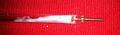
Game Cube opening tool
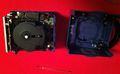
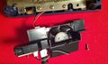
GameCube disassembly
Safely take apart all the parts
Game Cube top removal
Game Cube front removal
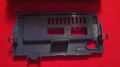
Game Cube back removal
Game Cube fan removal
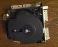
Game Cube cd reader removal
Game Cube cpu removal
Game Cube main parts


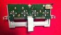
Gamepad Connectors
The gamepad will use the gamecon_gpio_rpi driver which use the following GPIO rev2 pins:

Carefully identify each pins :
- 3.3V
- 5V
- PAD1
- PAD2
- PAD3
- GROUND
I found an adapter from an old dvd reader to connect the GPIO to the GameCube front panel to easily connect wires to the GameCube original ribbon cable. Each ( port 1 and port 2 ) gamecube controller should be connected to
- Pin2 to PAD2 or PAD3
- Pin3 to GROUND
- Pin6 to 3.3V
- Led to 5V
- Reset switch to PAD1
I used a continuity tester and the following connecter pinout to identify the wire.

and here is the result :
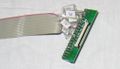
GPIO to GameCube gamepad

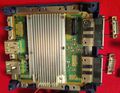
Power supply
My goal is to reuse the GC’s original power supply and to allow the use of a standard power supply.
To do so, you’ll need a DC/DC converter that will take any DC power under 24v to transform it in the 5V DC needed by the Pi. You can find that on ebay by searching "3A UBEC 5V". The original power switch and the fan are also functional :
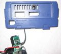
GameCube power supply

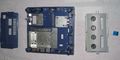
You’ll need to place the DC/DC converter between the GC’s power supply and the Pi:
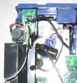
GameCube power supply unit

and the output of the power supply is powering the Pi. I do not use the micro USB port to power the pi because :
- it's allow me to spare some space and put the sd card in front of the gamecube;
- it's allow better connectivity.
Result
The Raspberry pi’s SD card can be inserted in the gamecube’s memory port. The HDMI and Ethernet ports from the Pi are prolongated to the GC’s ports Here is the result :
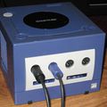
Retrocube front
Retrocube back
Retrocube inside


Software
The Pi is running RetroPie.
RetroPie installation and configuration
You’ll need to download RetroPie from their website petrockblockhttp://blog.petrockblock.com/retropie/retropie-downloads/
Then we’ll copy the image onto the SD card using linux:
dd if=Downloads/RetroPieImage_ver1.9.1.img of=/dev/rdisk2 bs=1m
Then boot the RetroPie with a HDMI screen and a usb keyboard then
- Press F4 to exit the menu
- Launch the raspi-config command
sudo raspi-config
and follow these steps
- * set date and time
- * set keyboard layout
- * overclock medium
- * expand the root fs
- * memory split 128M
F4 # to quit the menu
sudo raspi-config
  > set date and time
  > set keyboard layout
  > overclock medium
  > expand the root fs
  > memory split 128M
sudo reboot
F4 # to quit the menu
# At this step it is possible to connect to the pi using SSH : ssh pi@raspberrypi.local
sudo apt-get update
cd RetroPie-Setup
chmod +x retropie_setup.sh
sudo ./retropie_setup.sh
  > UPDATE SETUP (4)
  > UPDATE BINARIES (5)
  > SETUP
        2 Latest firmware
sudo reboot
sudo ./retropie_setup.sh
   > SETUP
       11 install multi console gamepad
       12 Enable gamecon_gpio_rpi with SNES-pad config
Gamecon patch and compilation
The original gamecon driver has some defects witch GameCube gamepad.
sudo cp -r /usr/src/gamecon_gpio_rpi-0.9 /usr/src/gamecon_gpio_rpi-0.9-bak
cd /usr/src/gamecon_gpio_rpi-0.9
sudo vi gamecon_gpio_rpi.c # Change the following lines :
sudo modprobe -r gamecon_gpio_rpi && sudo dkms remove gamecon_gpio_rpi/0.9 --all && sudo dkms install gamecon_gpio_rpi/0.9 && sudo modprobe gamecon_gpio_rpi map=0,0,3,0,0,3
echo "gamecon_gpio_rpi map=0,0,3,0,0,3" >> /etc/modules
sudo /etc/modules # To verify the new added line
sudo reboot
To disable some emulators, backup the original config file :
sudo cp .emulationstation/es_systems.cfg .emulationstation/es_systems.cfg-orig
then edit the configuration file to delete the emulator you don't want to see in the menu
Reset button
To allow the original reset button to quit a running game, we need to install pidkey, a software which trigger a keyboard event when the pooled GPIO is put to ground :
wget https://codeload.github.com/mmoller2k/pikeyd/zip/master
unzip master
cd pikeyd-master
make
sudo cp pikeyd /bin/pikeyd
sudo vi /etc/pikeyd.conf
/etc/pikeyd.conf is the config file which contain the key and the GPIO number
KEY_ESC 2
sudo vi /etc/rc.local
Add the following line to rc.local :
/bin/pikeyd &
Overclock
I put a thermal dissipator on the RaspberryPi CPU before over clocking. My over clock setting are (in /boot/config.txt) :
arm_freq=1050
core_freq=540
sdram_freq=630
over_voltage_sdram=6
over_voltage=6
gpu_mem=128
avoid_safe_mode=1
avoid_pwm_pll=1
With this settings my Raspberry Pi is working well and thank to the GameCube fan, it's temperature is below 50°C
Performance
If you need more power for some emulator, you can follow the following steps :
Use static ip address
To configure in the file /etc/network/interfaces
Disable some services
sudo apt-get install rcconf sysv-rc-conf
rcconf
Here is the list of services started at boot :
- alsa
- console-setup
- dphys-swapfile
- fake-hwclock
- kmod
- procps
- ssh
- sudo
- switch_cpu_governor
- udev
Edit initab (sudo vi /etc/inittab) to comment the following lines :
2:23:respawn:/sbin/getty 38400 tty2  (2 to 6)
T0:23:respawn:/sbin/getty -L ttyAMA0 115200 vt100
GamePad configuration
PiFBA
vi /home/pi/RetroPie/emulators/pifba/fba2x.cfg
N64
vi /home/pi/RetroPie/emulators/mupen64plus-rpi/test/InputAutoCfg.ini and add the following :
[Gamecube controller]
plugged = True
plugin = 2
mouse = False
AnalogDeadzone = 4096,4096
AnalogPeak = 32768,32768
DPad R = hat(0 Right)
DPad L = hat(0 Left)
DPad D = hat(0 Down)
DPad U = hat(0 Up)
Start = button(7)
Z Trig = button(4)
B Button = button(1)
A Button = button(0)
C Button R = button(3)
C Button L = button(5)
C Button D = button(2)
C Button U = button(6)
R Trig = button(6)
L Trig = button(5)
Mempak switch = key(109)
Rumblepak switch = key(114)
X Axis = axis(0-,0+)
Y Axis = axis(1-,1+)
References
GameCube opening http://www.ifixit.com/Teardown/Nintendo+GameCube+Teardown/1727
gamecon_gpio_rpi driver https://github.com/petrockblog/RetroPie-Setup/wiki/gamecon_gpio_rpi
GameCube gamepad pinout http://www.int03.co.uk/crema/hardware/gamecube/gc-control.html
RetroPie http://blog.petrockblock.com/retropie/
GameCube gameconhttp://www.davesblog.com/blog/2013/12/27/hacking-the-gamecube-controller-on-the-raspberry-pi/